Electropneumatics
Electropneumatics simulator with a real electrical rack
Wire 24 V circuits with push buttons, relays, time relays and sensors, and drive solenoid valves and cylinders — with the live ladder (EN 61082) diagram next to the 3D bench.
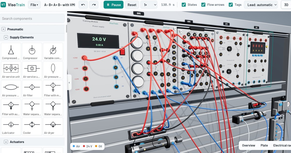
Electrical components
Power and operation
Power supply 24 V DC, push-button and indicator module (detented and momentary), emergency stop, lamps and buzzer.
Relays and timers
Three-fold relay modules (NO/NC contacts), on-delay and off-delay time relays, counters.
Sensors
Magnetic proximity switches on the cylinder barrel, inductive, capacitive and optical sensors, pressure switches, roller limit switches.
Solenoid valves
3/2 and 5/2 single-solenoid, double-solenoid (impulse) and 5/3 valves, valve terminals.
Graded electropneumatics exercises
- Direct electrical control — Push button S2 of the electrical push-button module controls a solenoid valve: the double-acting cylinder extends while S2 is held and retracts when it is released.
- Self-holding relay: start and stop — A short press on S2 (start) extends the cylinder and it stays extended. A short press on S3 (stop) retracts it. Use a relay with a self-holding contact; stop must win if …
- Automatic return with a proximity sensor — A short press on S2 extends the double-acting cylinder; a magnetic proximity sensor at the front end position makes it return automatically. It then stays retracted.
- Timed return with a time relay — A short press on S2 extends the cylinder. When it reaches the front end position it must wait about 2 seconds (at least 1.5 s) and then return automatically.
- Position indicator lamp — The cylinder is controlled by S2 (extends while held). Indicator lamp H1 must be on only while the cylinder is fully extended.
- Electropneumatic sequence A+ B+ A− B− — Cylinders A and B with 5/2 double solenoid valves and magnetic proximity sensors at both end positions. A press of S2 runs A+ B+ A− B− once.
- Electrical stepping chain: A+ B+ B− A− — Build an electrical stepping chain with relays for A+ B+ B− A− (one cycle per press of S2). Each step relay latches itself, is set by the previous step AND its sensor, an…
- Blinking signal with time relays — While the detented switch S1 is on, indicator lamp H1 must blink: about 1 s on, 1 s off (each phase between 0.5 s and 2 s). When S1 is switched off, H1 goes off.
- Electrical blocking signals: A+ B+ B− A− with a group relay — Cylinders A and B with 5/2 double solenoid (impulse) valves and proximity sensors. One press of S2 runs A+ B+ B− A− once. Wired directly (S2 → Y1 of A, a1 → Y1 of B, b1 →…
- Find the electrical blocking signal: A+ A− B+ B− — Cylinders A and B with 5/2 double solenoid (impulse) valves and proximity sensors. One press of S2 runs A+ A− B+ B− once. Wired directly (S2 → A+, a1 → A−, a0 → B+, b1 → …
Example circuits
- Direct electropneumatic control — Momentary button S2 energises coil Y1 of a 5/2 single solenoid valve: the cylinder extends while the button is held.
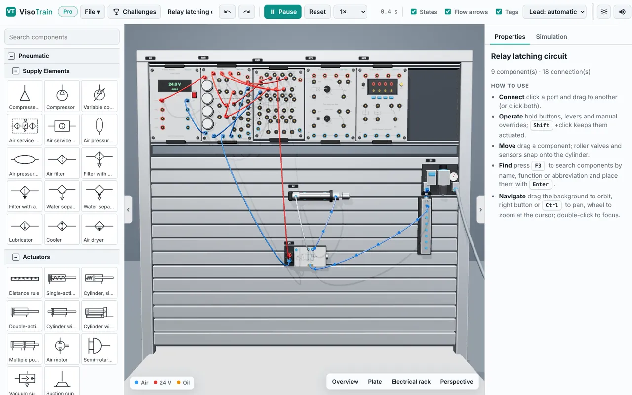
- Relay latching circuit — S2 starts, S3 stops (stop dominant). K1 holds itself via contact 11–14; contact 21–24 drives Y1 and 31–34 lights H1.
- Continuous cycle with sensors — Detented S1 starts the cycle. B1 (retracted) via K1 drives Y1; B2 (extended) via K2 drives Y2 of the 5/2 double solenoid valve.
- Timed return (time relay T1) — S2 extends (Y1). When B2 detects the end position, T1 counts 2 s and contact 15–18 drives Y2 to retract.
- A− B+ A+ B− with VMPA valve terminal — Two cylinders driven by the two bistable slices of the VMPA terminal (coils 2-14 / 2-12 for A, 3-14 / 3-12 for B). A starts extended. S2 START latches K1 → A− ; sensor A0 (via K1) → B+ ; sensor B1 energises K2, which drops K1 and gives A+ ; sensor A1 (via K2) → B−. S3 extends A by hand (home position).
- Cycle counter — Continuous cycle that stops after 3 cycles: the counter NC contact 11–12 interrupts Y1. S2 resets the counter (R1/R2).
Frequently asked questions
What is electropneumatics?
Electropneumatics combines pneumatic actuators and valves with electrical control: solenoid valves are switched by relays, push buttons, sensors or a PLC.
Can I build a self-holding (latching) relay circuit?
Yes, it is one of the graded exercises: start/stop with stop dominance, relay K1 holding itself through its own NO contact.
Is there a ladder diagram?
Yes, the electrical circuit is drawn live as numbered current paths between +24 V and 0 V (EN 61082), synchronised with the 3D bench.